
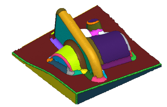
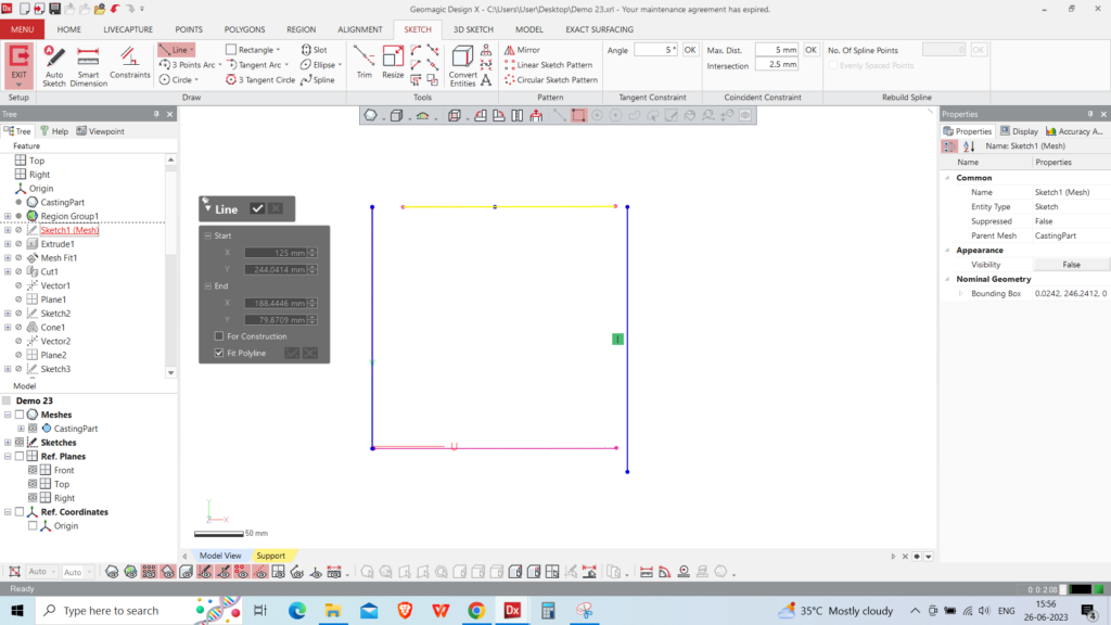

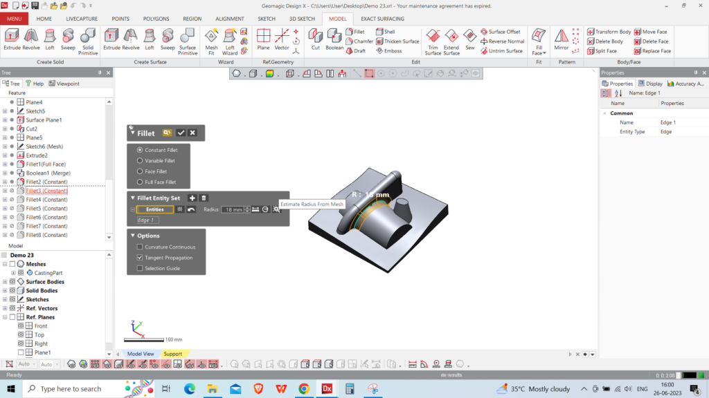
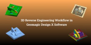
As-Built Technique: In the as-built approach, we make sketches from the cross-sections that will be constrained to align
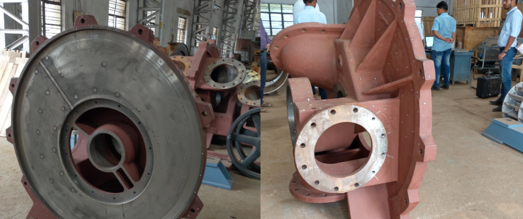
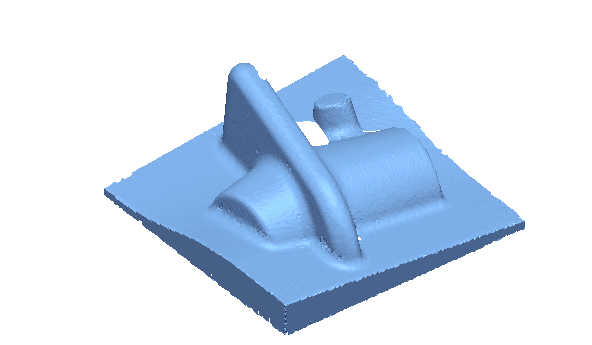
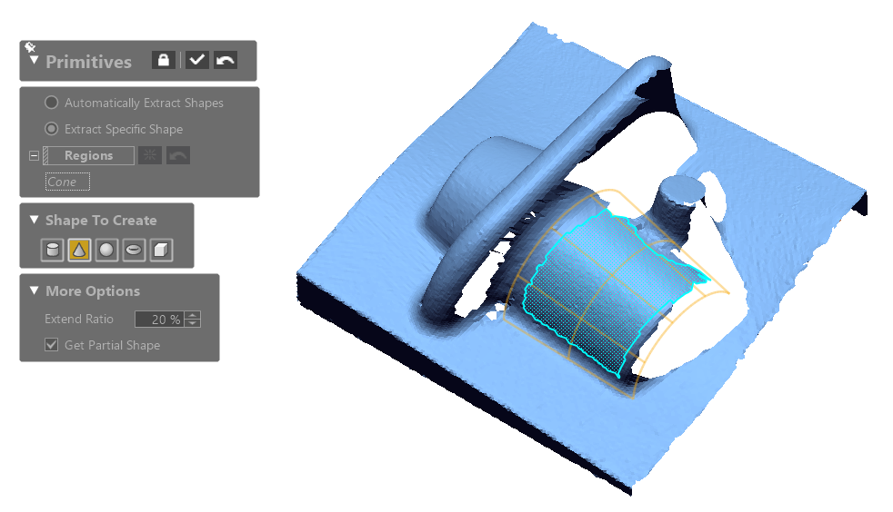
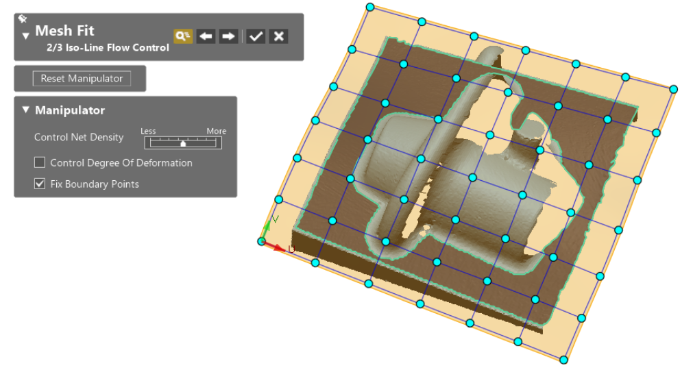
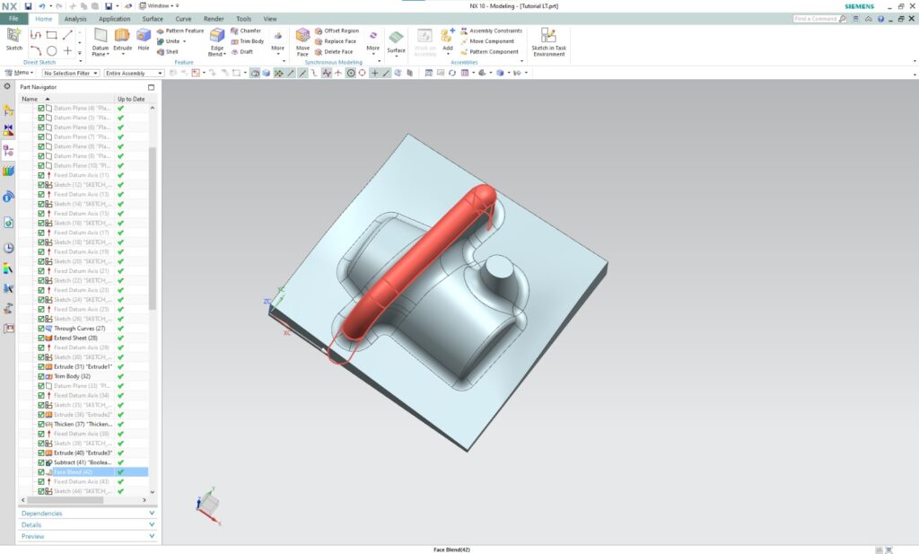
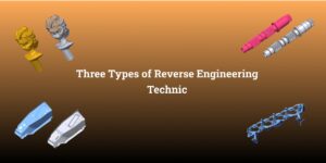
3D Reverse engineering is a 3D modelling process from the 3D scan that allows us to recreate
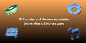
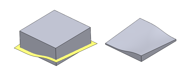
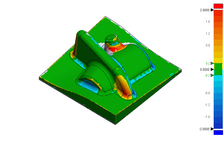
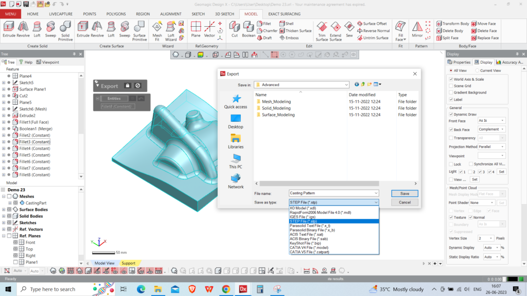
The deliverables of 3D scanning and reverse engineering can vary depending on the project’s requirements and end applications.
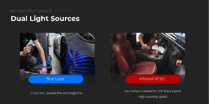
Introduction: The Freescan Combo 3D scanner is an extraordinary device that combines the utmost metrology-grade precision with a