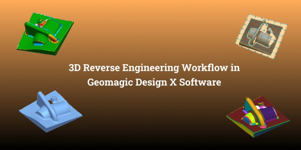
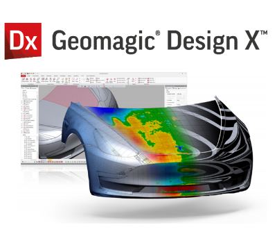
3D Reverse engineering is a 3D modelling process from the 3D scan that allows us to recreate 3D models from 3D scanned objects. Among the leading software solutions in this field of reverse engineering, Geomagic Design X stands out for its comprehensive set of tools and advanced capabilities. In this blog, we will explore the 3D reverse engineering workflow in Geomagic Design X using some partial 3D scan data.
3D Scan Directly or Import the 3D scan data in Geomagic Design X :

The first step in the Geomagic Design X 3D reverse engineering workflow is to acquire the necessary 3D scan data from the physical object by connecting various scanner technologies, such as laser scanning or structured light scanning or, to capture the object’s geometry and surface details. Alternatively users can also import the 3D mesh file into the Geomagic Design X software for further processing.
Region Segmentation
When you begin the process of 3D reverse engineering using Geomagic Design X Software, the initial step involves dividing the scan data into various segments. Each of these segments can then be individually chosen to either generate CAD features based on the scan data or to access the scan data itself. This means you can interact with the scan data similar to how you would work with a CAD model in CAD software. For example, if you want to sketch something, you can directly select a planar region instead of having to create a plane from scratch.


3D Scan Alignment:
Once the data is imported, the 3D scan file will be in the machine (3D scanner ) coordinate system , moving the machine coordinate systems to the world coordinate is called an alignment.Geomagic Design X offers powerful tools to process and align the scanned data to the world coordinate systems . The software provides automated and manual alignment options, ensuring accurate positioning of the scanned data for further processing.


Create 2D As built & Design Intent sketch from Mesh file
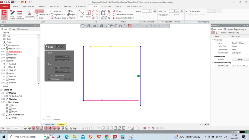
Users have the freedom to utilise any of the system planes or select specific faces from the mesh file in order to generate cross sections of the mesh file for creating both as-built and design intent sketches. The as-built sketch accurately represents the cross section as a reference, disregarding any manufacturing errors. On the other hand, the design intent sketch creates a sketch with geometric constraints, capturing the intended design specifications.
CAD model generation
Geomagic Design X offers a comprehensive range of CAD modeling features, empowering users to create various forms from sketches. These include options such as exclusion, revolve, sweep, and loft, enabling users to achieve their desired design outcomes.Here in this case study we extruded the body using the initial sketch we have extracted.

Powerful Surface Creation
Geomagic Design X possesses the capability to generate complex surfaces from the scanned region. Users can employ either the mesh fitting technique or the automated extraction of loft surfaces to create these surfaces. This versatile functionality allows for the creation of intricate and diverse surface geometries to meet specific design requirements.
We have selected the freeform region so software can extract the 3D mesh fit surface.

Mesh Fit function In Geomagic Design X
Boolean operations :
In Geomagic Design X, users have the ability to carry out Boolean operations. In this particular example we have used a surface as a tool and a solid as a targeted body. Moreover, you can create a variety of Boolean operations like cut, merge, split, and unite for both surface and solid entities within the Design X environment.

Extracting CAD primitives (Surface & Solids features )
Wizard functions are among the powerful features in Geomagic Design that enable the automatic extraction of various CAD features from segmented scan regions. These functions offer a convenient and efficient way to extract and incorporate different types of CAD elements, enhancing the overall design process.
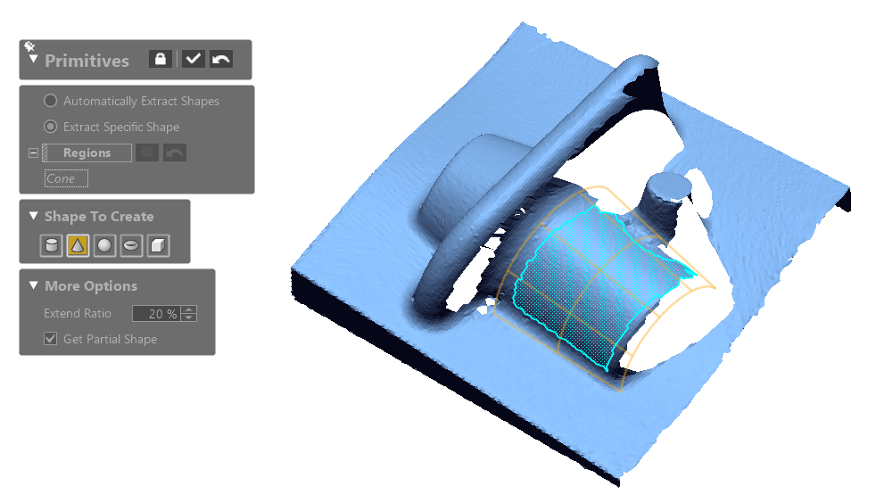
Points that software uses for feature extraction
CAD Model Creation and Editing: Once the surface reconstruction is complete, Geomagic Design X allows you to create a CAD model based on the scanned data. The software provides a range of powerful tools for creating and editing CAD features such as curves, surfaces, and solids. You can refine the model’s geometry, add details, and make design modifications as needed. Geomagic Design X’s intuitive interface and robust feature set make CAD modeling a seamless and efficient process.
Estimating the right radius
Geomagic Design X offers various types of fillet options that automatically calculate the radius from the CAD edge. It displays a suggested radius that the user can adjust according to their preference. The user can choose to either stick with the suggested value or set a specific rounded value.
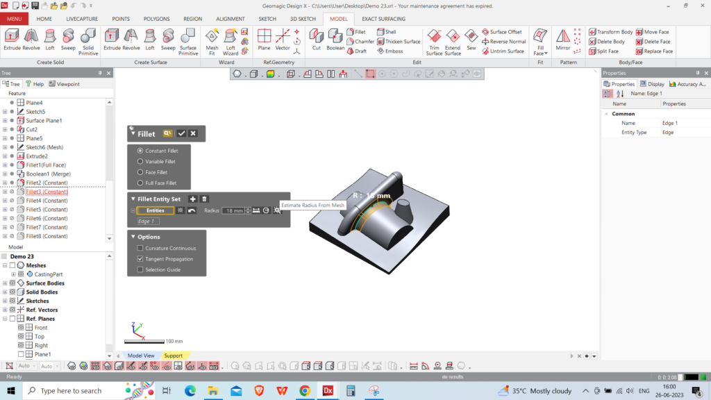
Fillet option in Geomagic Design X
Validation & Quality Control
After creating the CAD model, it is crucial to validate its accuracy and quality. Geomagic Design X offers advanced tools for comparing the scanned data to the CAD model, allowing you to identify deviations and perform quality control checks. The software provides visual deviation analysis, cross-section analysis, and other inspection tools to ensure that the CAD model accurately represents the physical object.

- Colour map deviation comparing scan & the final CAD.
- Export as neutral CAD or Live Transfer to CAD
- Neutral CAD – Dump Solids
Once you are satisfied with the CAD model, Geomagic Design X allows you to export it in various industry-standard formats, such as STEP or IGES, for further utilisation. The exported model can be seamlessly integrated into CAD/CAM systems or used for downstream processes such as 3D printing, manufacturing, or simulation.
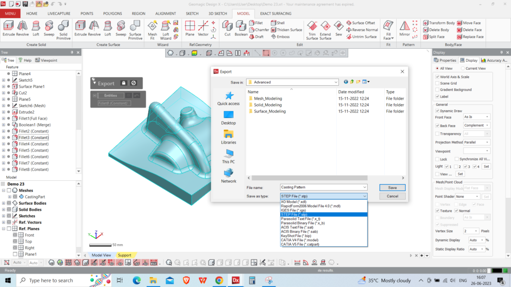
Dump solid file export options inside the software
Live transfer to CAD
After you finish your parametric modelling in Geomagic Design X, all those parametric features you’ve created will be seamlessly moved over to your preferred CAD software such as SOLIDWORKS, UNIGRAPHICS, CREO, etc… This has a significant advantage: it lets you bring the entire modelling history within your CAD software, In other words, you can have the complete design history in your CAD software even if you haven’t modeled it there initially. This is made possible through the Design X live transfer function. This live transfer function’s key benefit is to save time and effort while ensuring the creation of highly accurate design features from the 3D scan.
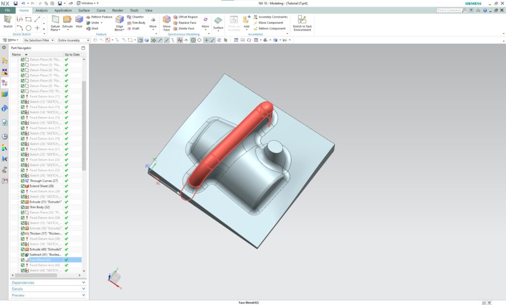
Live Transfer to Unigraphics
Conclusion:
We utilised the example above for multiple reasons:
The scanned object has both a freeform and prismatic shape.
The geometric attributes of the revolve feature are oriented along different axes tilted to each other.
The object itself was not fully scanned, resulting in partial data for the design.
Given these complexities, accomplishing 3D reverse engineering of such a shape using conventional CAD software would demand a minimum of 2 hours.
However, we could streamline the process thanks to the robust functionalities within Geomagic Design X, including modeling wizards and surface fitting tools. As a result, we could complete the same task in just 15 minutes. This highlights the impressive capability of Geomagic Design X as a powerful software that substantially reduces the time required to transition from the real world to the CAD environment.
What's next ?
Enquire Now
As-Built Technique: In the as-built approach, we make sketches from the cross-sections that will be constrained to align
3D Reverse Engineering Workflow in Geomagic Design X Software
3D Reverse engineering is a 3D modelling process from the 3D scan that allows us to recreate
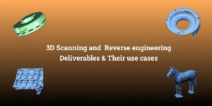
The deliverables of 3D scanning and reverse engineering can vary depending on the project’s requirements and end applications.
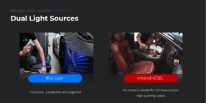
Unique Key features of Freescan Combo
Introduction: The Freescan Combo 3D scanner is an extraordinary device that combines the utmost metrology-grade precision with a

