

Ever wondered what raw materials are employed to make private buses safe and reliable for inter-state travel? Do you think it is aluminium or iron? You are partially correct! Most of the bus parts are made out of composite materials like FRP (fibre reinforced polymer) as they possess superior properties to other metals. They are extremely versatile, lightweight, and efficient and hence, result in lighter, robust and durable manufactured parts.
A composite tooling manufacturer based out of Andhra Pradesh; India approached us to streamline the inspection process of the Front & Rear Fascia of private buses being manufactured by them. Their team was inspecting the manufactured parts manually which led to judgemental errors. Based on their judgement they were deciding whether more composite material needs to be added to the part or remove from the part. Since buses are not small, one can imagine the size of the front and rear fascia of these buses. Each part was approximately 4 metres long and 3 metres wide. Manual methods and conventional tools made the inspection process of these huge parts time-consuming and laborious. Plus, a lot of re-work had to be done on the defective parts.
Therefore, our client was hunting for a solution that can help them in comparing the manufactured part with their CAD data quickly and effectively. It is crucial to maintain the uniform width of the front and rear fascia of private buses as it may impact passengers negatively in case there is an accident.
After an initial consultation and an online demo, the team was determined to go ahead with the 3D Scanning Solution provided by Precise3DM. The solution involved Precise3DM’s team visiting their manufacturing facility with an appropriate 3D Scanner and related accessories but integral to the solution was the 3D Scanner – FreeScan UE7.
What is FreeScan UE7?
It is an easy-to-use and lightweight new-generation handheld 3D Scanner developed to provide a high-precision (0.02mm) digital inspection experience. It projects blue-coloured Class 2M (eye-safe) laser light on the objects to be scanned and captures data of the surface in the form of a Point Cloud. Businesses can trust the 3D Scan output of this 3D scanner as it exhibits very stable repeatability with a scan speed of 6,50,000 points/sec. One can acquire the scan output in the file formats – OBJ, STL, ASC, PLY, P3, 3MF.
It supports the scanning of black and reflective surfaces to accommodate a wide range of scanning applications. It weighs just 670 grams and works on 12V. This 3D scanner model is approved by CE, FCC, ROHS, WEEE and KC. It is highly suitable for industries like Automotive, Transportation, Aerospace industry, Molding inspection, Energy generation, Machinery manufacturing, etc. Do watch out the video below to get acquainted with the features of this 3D Scanner.
Workflow
Step 1: Calibrate the 3D Scanner
Step 2: Place the part to be scanned on a platform that makes it easy to scan. (You can even 3D scan the bigger parts when they are in assembled condition as well.)
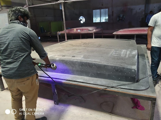
Step 3: Stick markers on the surface of the part to ensure a high-quality scan output. All markers are allotted a unique reference ID. Since the surface is not transparent, developer spray is not required to be sprayed on the surface and scanning is done in normal mode.
Step 4: Scan the entire surface of the part in a single go.
Step 5: Register the Point Cloud and convert it into an .STL data file
Step 6: Import the .STL data file into the dedicated-inspection software Geomagic Control X and align it to the 3D CAD model.
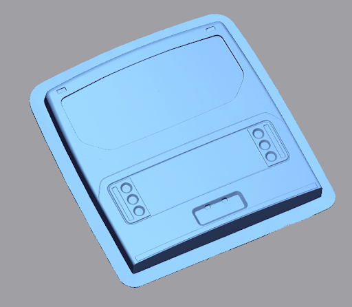
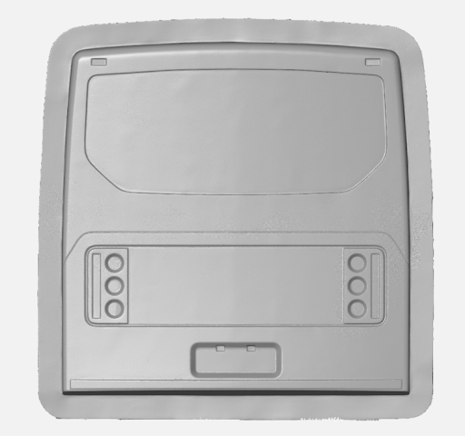
Final 3D Scan Model
3D CAD Model
Step 7: Superimpose the cleaned-up 3D model over the existing 3D CAD model of the part.
Step 8: After that, the software automatically shows the deviations in the part. Our client’s team can now accurately pinpoint the deviations and add or remove material precisely to make the surface uniform.
As depicted in the image below, the positive comparative values show excess material and negative values show a high shortage of material. The upper and lower tolerance limits specified by the client are +5mm and -5mm in thickness. The green colour represents deviations within the tolerance specified by the client. Red and orange show excess material beyond the higher tolerance limit and light blue and dark blue show a shortage of material beyond the lower tolerance limit.
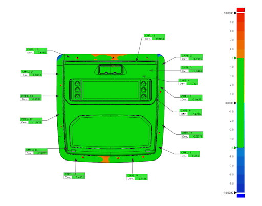
The image above represents a visual display of deviations. Geomagic Control X can also display the deviations in tabular format for your convenience. The inspection report can also be exported as PDF. Check out other blogs on Geomagic Control X by clicking here (add a hyperlink to some Geomagic Control X blogs) and understand the capabilities of the powerful inspection software.
In total, it took us 2 hours to make the first part scan-ready and then scan it. After that, it took us just 30 minutes to inspect it. After that, we utilized the Batch processing functionality of Geomagic Control X to complete the inspection of the remaining parts in a jiffy.
Impact of our 3D Scanning Solution
- Reduction in inspection time by 80%
- Reduced re-work of parts
- Negligible human intervention
- Improvement in team’s morale
- Happy customers
- Increase in ROI by 50%
Our motto is to deliver value for money and help businesses in adopting a digital culture. If you are also looking for 3D Scanners for your business but do not know which 3D Scanning Solution is suitable for your business, take a chill pill! Our Sales team will guide you throughout your journey of adopting 3D Scanning technology.
You can also get a quick quote for FreeScan UE and Geomagic Control X by clicking here.