Automotive Benchmarking is the process of analysing a Vehicle completely by dismantling a vehicle and creating a complete study on dimensions and performance of a vehicle. In this blog we are going to show you a complete Teardown Benchmarking of a car.
The main objective of the project is to compare and analyse the NVH analysis of the BIW along with the cross-members. We analyse and compare the physical vibration test results and develop a definite element model to match actual test results. This will be used as a reference to run ideal tests using stimulation techniques. To achieve the final output we use 3D scanning, reverse engineering, vibration testing, CAE analysis, material testing and obtaining data regarding the mechanical properties of each part after material testing.
Scope
We have defined set of tasks that has to be executed to achieve the output
Teardown of the entire vehicle and documentation of the complete process
3D Scanning and photographic documentation at each step.
Drafting Bill of Materials at each step of the teardown to correspond sub assembly modelling & Assembly documentation, Material composition analysis & Grade identification, Suggestion of alternate materials, Correlation of Grade physical properties with actual measured properties on critical parts.
Equipment's used for this Benchmarking
We have defined set of tasks that has to be executed to achieve the output
Teardown of the entire vehicle and documentation of the complete process
3D Scanning and photographic documentation at each step.
Drafting Bill of Materials at each step of the teardown to correspond sub assembly modelling & Assembly documentation, Material composition analysis & Grade identification, Suggestion of alternate materials, Correlation of Grade physical properties with actual measured properties on critical parts.
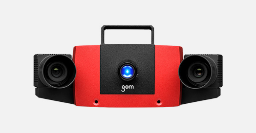
GOM Compact
While mechanical measuring systems capture data in a point-based or linear manner, optical measuring systems provide full-field data about deviations between the actual 3D coordinates and the CAD data. As this measuring data contains all the object information, in addition to the surface deviations from the CAD, the software also automatically derives detailed information such as GD&T, trimming or hole positions.
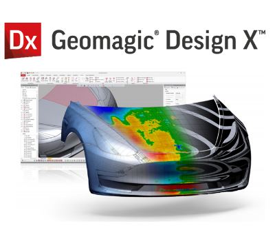
Geomagic Design X
Geomagic Design X is the Industry-leading software dedicated to Digital Reverse Engineering applications. Its comprehensive features enable CAD designers and 3D experts to use the 3D scan as a foundation to create history-based design intent and accurate as-built CAD and NURBS surfaces.
Geomagic for Solidworks
Geomagic for SOLIDWORKS is a reverse engineering software plugin exclusively developed to integrate into your SOLIDWORKS workflow. This will unlock advanced capabilities allowing you to directly connect your 3D scanner into Solidworks. You will be able to 3D Scan, Import Point Clouds, Create mesh files, and subsequently use 3D Scan models as a reference to extract features, CAD sketches, complicated surfaces, and solids.
Mechanical Machineries/Tools:
Grinding Machine
Drilling Machine
Chisel
Gas Cutter
Hammer
Spectrometer
It is an equipment that is used for material testing, it is essential to separate the metrology of a spectral component in a materialistic State.
Universal Testing Machine
It is used to acquire accurate values of Tensile strength, Yield Strength and Elongation of an object.
Total Material
It is used to segregate the materials according to the chemical composition & Material properties of the Vehicle parts.
Step by Step Process of teardown Benchmarking
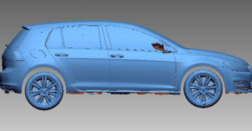
Assembled car 3D Scanning
There are several steps that are involved before 3D scanning of a car in assembled condition.
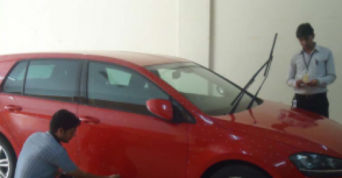
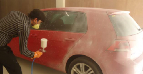
First the vehicle was cleaned well and placed in a closed Environment, where the vehicle will stay free from dust.
For Scanning reference target sticker is placed throughout the vehicle
A white powder spray is applied over avoid reflection While scanning
Finally the Vehicle is scanned completely and the Scan data has been acquired.
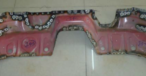
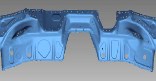
Live Vehicle Image
Scan Data
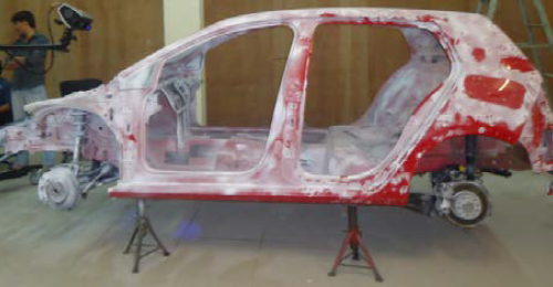
Tear Down
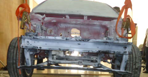
After scanning the vehicle in fully assembled condition and Vehicle is torn down at BIW level. Basically everything in the vehicle is torn down leaving only the Chassis and cross members of the vehicle for 3D scanning.
Assembled Condition
BIW
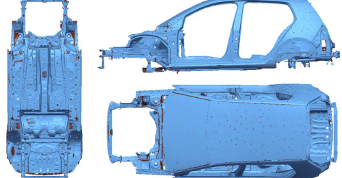
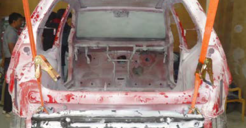
Scanning of BIW with Cross members
In this process the vehicle is scanned on the Exterior, Interior and Under body of the Vehicle in BIW Condition.
Scanning of BIW without Cross members
In this step, we have removed the cross members and scanned the remaining area of the vehicle, Which is not covered in the previous process
Scanning of Individual Cross members
While in BIW condition, We will not be able to get a complete scan data of certain parts of the vehicle, So these parts are removed separately and scanned for getting an accurate data of those parts.
NVH Testing
NVH testing is one of the primary objectives of this particular project and accurate results were acquired with Various Testing and analysis were done.
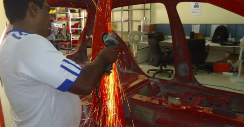
Cross Members tear down
This step celebrated the tear down of cross members into Individual parts, once the BIW scanning with cross Members is completed.
Removing each part is done very carefully and plenty of details are documented like Weight, thickness, type of weld (spot weld(2T &3T), laser weld, arc weld and plug weld).
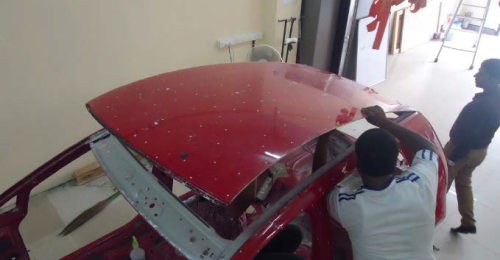
We have separated BIW parts into seven subassemblies
Side outer LHS panel assembly
Side outer RHS panel assembly
Roof assembly
Dash and Cowl panel assembly
Rear panel assembly
Floor assembly
Engine compartment assembly.
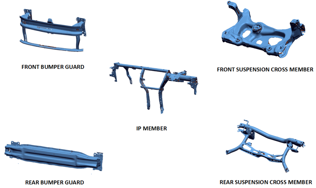
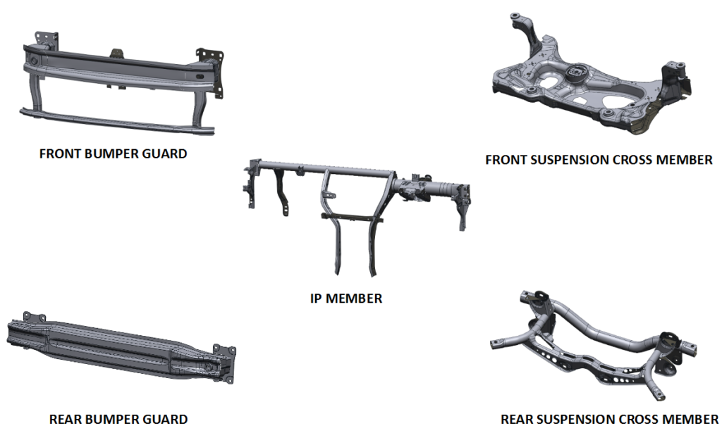
We have separated cross members into five subassemblies
Front bumper guard assembly
Rear bumper guard assembly
Front suspension cross-member assembly
Rear suspension cross-member assembly
Instrument panel assembly
3D scanning of Individual parts
These are parts that are removed from the BIW or Cross members assembly and scanned Individually and modelled separately.
While developing a CAD model out of the scan data, BIW CAD modelling is done according to each assembled part and subassemblies.
CAD models of outer panels, Inner panels, floor panels and underbody panels are done. Both the BIW and Cross members are modelled separately which gives us much more clear and accurate data.
CAD Model snaps of Panels and other cross members are provided below.
Material Testing
Inorder to obtain chemical composition of the both BIW and cross members parts Material testing is done. Spectrometer is to identify the right chemical composition of the parts.
After determining the chemical composition of the parts, Segregation of each part grade wise is done using Total Materia.
We found there were 30+ grades while material Testing.
Tensile Testing
Finally, we used a Universal Testing machine for Tensile testing, We have conducted this test to find the tensile strength, yield strength and Elongation of each material.