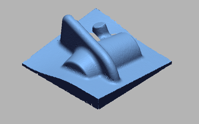
Overview
Digital measurement extraction of digitized shape
It is important to understand the accuracy and how accurately the 3D scanner captures and digitally extracts measurements from the object. Conducting a calibration accuracy check generally involves comparing the actual measurements of an object and the measurements obtained from taking a 3D scan of the object. 3D inspection software has built-in measurement tools that allow generating points, lines, and planes in a 3D model. Using these entities we can obtain exact measurements of complex models. We use Coordinate tools to generate planes from mesh selection. We can generate a perfectly straight line connecting the two points in the CAD model ( i.e, reference & derived) to extract the measurement. This method finds its application in Reverse engineering, Quality control, Custom fitted garments, Forensic documentation, Orthotics, Plaster casting, Crime scene investigation, Site modeling, and lay-outing.
WORKFLOW
 import 3d scan file (1).png)
Import 3D scan file
 Fit dimensions to measure.png)
Fit dimensions to measure
 measuring dimensions using 3d gd & t.png)
Measuring dimensions using 3D gd&t
 dimensions tabular column.png)
Dimensions tabular column
 Measuring 2d dimensions.png)
Measuring 2D dimensions
 Measuring 2d dimensions.png)
Measuring 2D dimensions
 2d dimensions table.png)
2D dimensions table
IMAGE
VIDEO
INDUSTRIES WE SERVE
WHAT'S NEXT?
RELATED BLOGS

Scan To Parametric CAD
Parametric cad consists of a history-based feature modeling tree that can be edited to make design
Read more
Scan To Parametric CAD
Parametric cad consists of a history-based feature modeling tree that can be edited to make design
Read more
Scan To Parametric CAD
Parametric cad consists of a history-based feature modeling tree that can be edited to make design
Read more


