OVERVIEW
Precise3DM digital inspection service provides advanced digital measurements of 3D scanned data or comparison between two digital files to perform a high level of shape and dimensional analysis that will help manufacturers have a complete study on manufacturing errors. Input for our digital inspection service will be two different CAD files or two 3D scanned files of separate parts or objects, or the CAD files of before manufacturing and 3D scanned files of end parts after the manufacturing. Once we perform the Inspection, we provide a customized pdf inspection report. In addition, we also offer all types of 3D scanning services in India if data.
Key Features
- • We accept any 3D scan output
- • CAD and no CAD inspection for 3D scanned parts
- • Even partial 3D Scans we accept to compare with CAD or extract digital measurement.
- • 3D Scan groups, point clouds, STL files are acceptable.
- • A decade of experience in 3D inspection application
- • We deliver output in customized or standard pdf format
- • More than 25 3D metrology specialists to support any large volume projects
Image Gallery
.png)
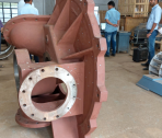
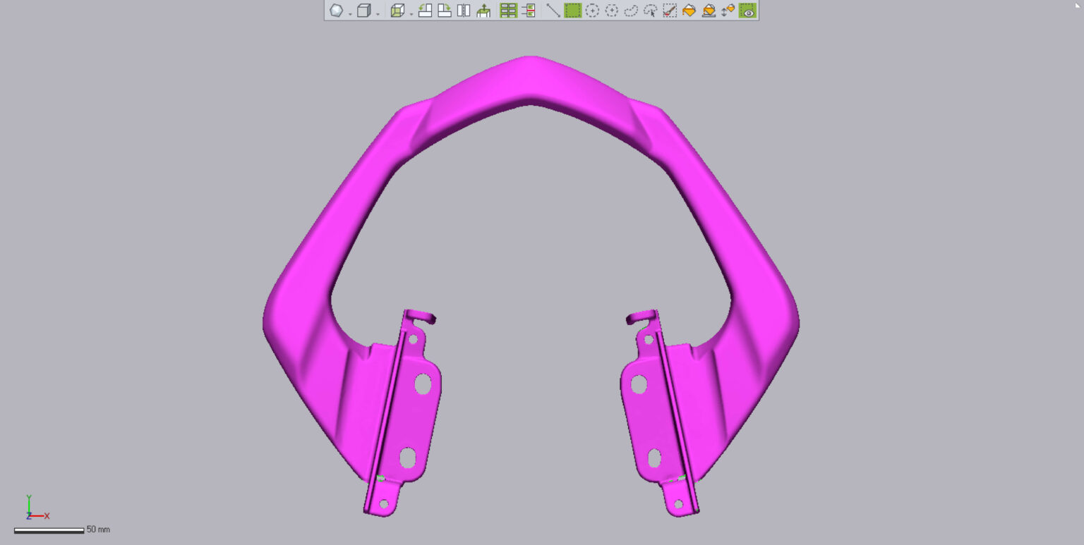
3D Inspection of sheet metal
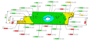
3D Inspection of sheet metal
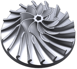
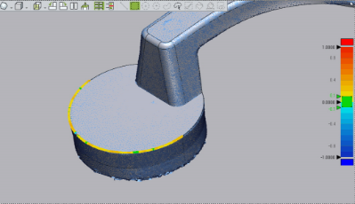
3D Inspection of impeller
3D Inspection of sheet metal
Video Gallery
Import Test (SCAN DATA) & Reference data (CAD DATA)
- - IGES File (.igs)
- - STEP File (.stp)
- - CATIA V4 File (.model)
- - CATIA V5 File (.catpart)
- - XO Model (.xdl)
- - Parasolid Text File (.x_t)
- - Parasolid Binary File (.x_b)
- - ACIS Text File (.sat)
- - ACIS Binary File (.sab)
- - RapidForm2006 Model File 4.0 (.mdl)
- - Binary STL File (.stl)
- - Ascii Point File (.asc)
- - CyberWare Binary File (.ply)
- - CyberWare Ascii File (.ply)
- - OBJ File (.obj)
- - Geomagic Points File (.pts)
- - Geomagic Polygons File (.fcs)
- - XO Model (.xdl)
- - 3D Studio File (.3ds)
- - AutoCAD DXF File (.dxf)
Alignment
3D Scan to CAD Alignment
The 3D Scan to CAD alignment tool helps in initial alignment of the measured data with the reference data automatically using Geomagic feature information. This alignment is used to position the measured data with the reference data as closely as possible before using advanced alignment tools. This scan can be used for aligning distant measured data, fully scanned data or partially scanned data.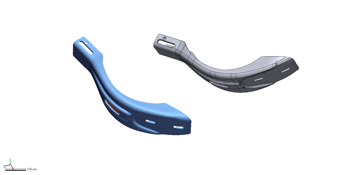
Best Fit Alignment:
The Best Fit alignment tool aligns measured data to the reference data using the overlapping regions between them. This tool is majorly used after using the 3D Scan to CAD alignment option. The Geomagic algorithm optimizes the rough alignment into more precise by minimizing the overall deviation between the measured data and the reference data.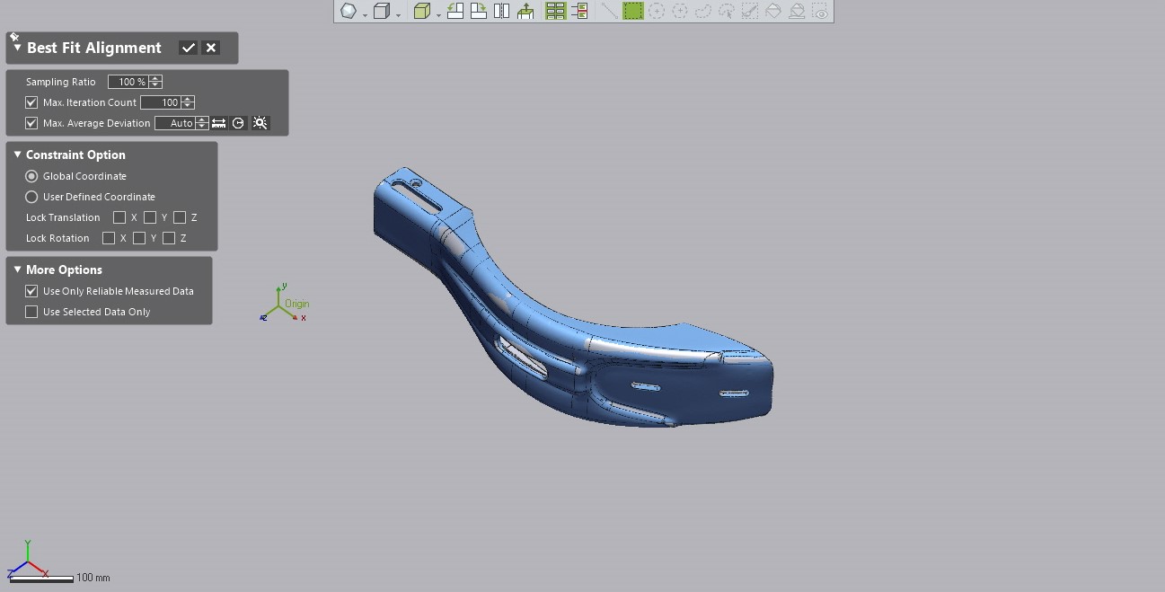
Datum Feature Alignment:
The Datum Alignment aligns measured data to the reference data by matching geometric features defined as datums. Datum Feature Alignment is useful for aligning measured data to the reference data by matching datum and geometric features.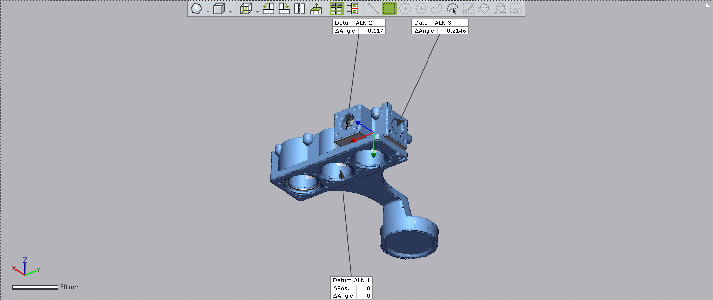
RPS Alignment:
RPS stands for Reference Point System. The RPS Alignment aligns measured data to the reference data by matching pairs of circles, slots, spheres or any other conical geometric shapes. RPS Alignment is best used for sheet metal parts as well as parts which does not have clearly defined geometric features.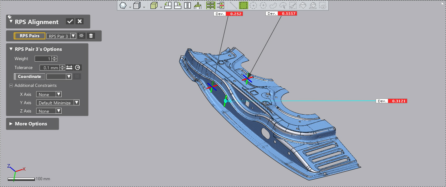
3-2-1 Alignment:
The 3-2-1 Alignment tool aligns measured data to the reference data by matching pair sets of datums constructed by three (Plane), two (Vector), and one (Position) points, and locking down all six degrees of freedom of the coordinate system. 3 points are used to define a primary plane, 2 points define a secondary plane perpendicular to the primary plane, and the last single point defines the final plane that is perpendicular to both the primary and secondary plane.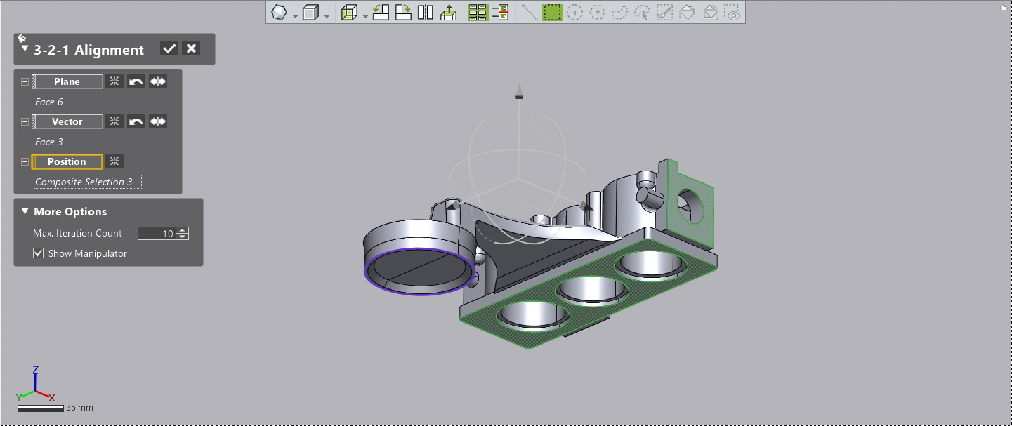
Type of 3D Analysis
1 . 2D Comparison
Creates a 2D plane that graphically illustrates the deviations between the reference data and the measured data. Easily accessible to compare the multiple points on the same plane. It is beneficial to compare the reference data and the measured Data on a sectional plane.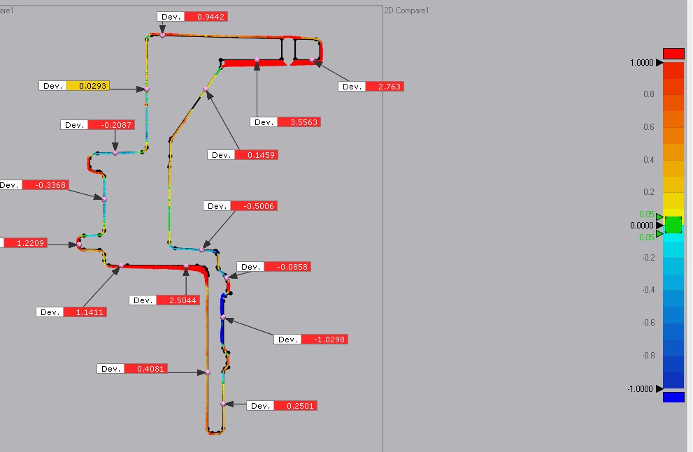
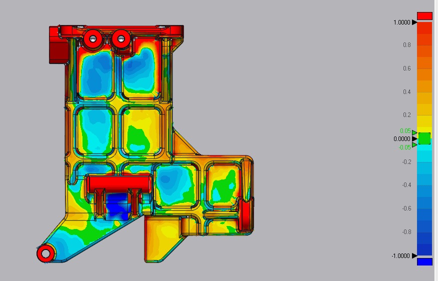
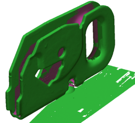
2. 3D Comparison:
Calculate and display the shape and form deviation between reference and measured. The 3D Compare tool analyses the deviation between the reference and measured data by projecting all paired points onto the reference data.The deviation is displayed with a color map that helps analyze negative and positive deviation plots through a whole part.
3. Sheet Metal / Boundary Comparison:
Sheet metal or boundary comparison is basically used for sheet metal parts that are hard to analyze in 3D or 2D Comparison. This tool is handy to compare the boundaries, holes, and trim lines of the sheet metal between the reference data and the measured data.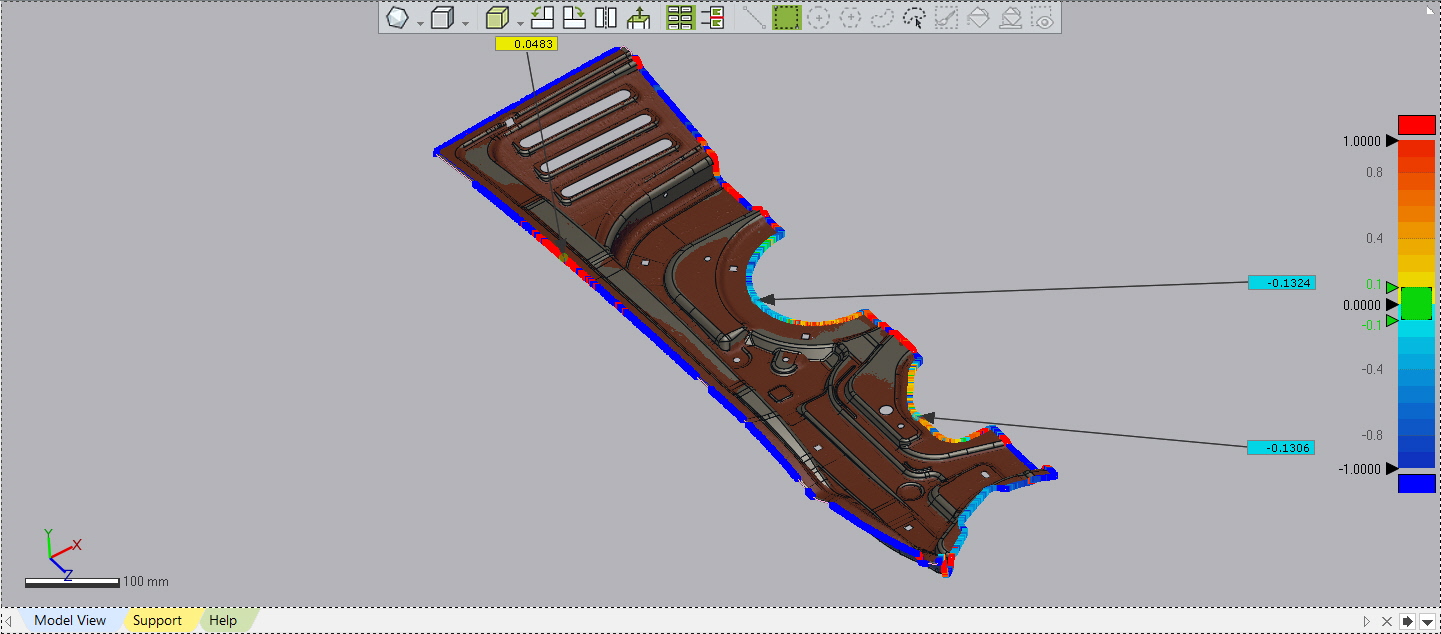
4. Virtual Edge Comparison & Measurement:
The Virtual Edge Comparison tool creates theoretical edges from rounded edges featured in a model and analyses the deviation between the reference and measured Data on the edges. In most cases of the real engineering world, a part has rounded edges modeled by filleting or abrasion caused by milling machine tooling. The Virtual Edge Comparison tool allows checking thedeviation on virtual edges created from the reference and measured data.
5. Profile Projection Comparison:
The Profile Projection Comparison tool creates a silhouette from the Reference and Measured Data, and analyses the deviation on it.It is useful in analysing the outer part of a plastic part and trim lines for sheet metal parts.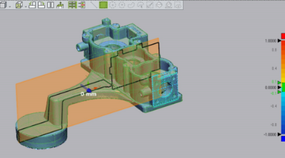
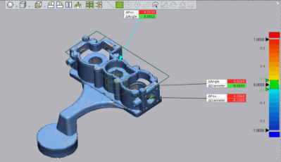
6. Geometry Deviation:
The Geometry Deviation tool compares geometries such as cylinders, circles, and planes between the reference and measured data.This tool is useful for analysing important geometries on a part and comparing the sizes of geometries.
7. 2D/3D Curve Deviation:
The 2D/3D Curve Deviation tool compares between curves created from the reference and measured Data, and displays the deviation results as coloured whiskers or points.This tool is basically essential to analyse freeform shapes, character lines and section curves.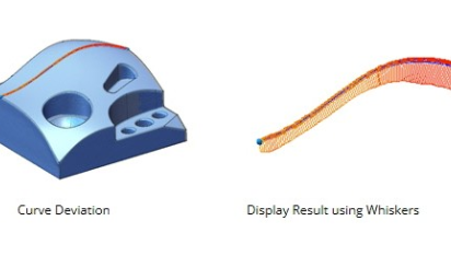
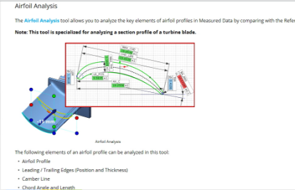
8. Airfoil and Twist Analysis:
The Airfoil Analysis tool allows you to analyse the key elements such as leading edge, trailing edge chord length and angle of airfoil profiles in measured data by comparing with the reference data. The 2D Twist Analysis tool analyses the deviation of twist angle between section profiles of the Reference and Measured Data.
CASE STUDY
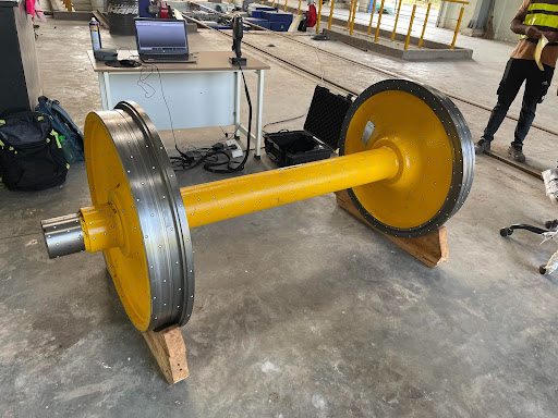
3D Inspection of Large Parts using Handheld Metrology 3D Scanning
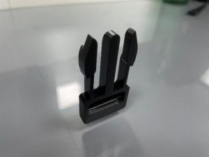
Post Print 3D Scanning & Digital Inspection of Bag Buckle(Male)
Are you an abroad client looking for a 3d scanning service in India? see how we help a French manufacturer
3D inspection software – Digital Quality inspection using Geomagic Control X
FAQs
What is 3D Inspection?
The physical part is 3D scanned by a 3D scanner and converted to 3D digital file, and imported into the 3D inspection software as a test object. CAD is also imported as a reference to the same interface and aligned to mesh(3D scan data). Subsequently, 3D shape & dimensional analysis is performed; as a result, it shows the difference between the manufactured part and the CAD design. This helps product makers to avoid manufacturing inaccuracy and miscalculation of ration.
How 3D Inspection helps in the automotive industry?
The automotive industry needs plastic parts inspection, sheet metal inspection, 3D Inspection of Automotive engine components, engine cooling systems, cluster assembly, carburettors, engine body cylinder heads 3D scanning and Inspection, gap and flush of doors, windows, electrical panes inspection, braking systems and reservoirs, car body components inspection, lighting systems inspection, bulbs and interiors, fuel supply systems, vehicle tires, air-conditioning, and passenger seats. We shall 3d scan all such types of parts and compare them with CAD and perform advanced 3D inspection analysis.
What CAD files do you accept?
We accept all types of CAD file extensions in our 3D metrology software, such as CATIA, UG, Creo, and we accept their own native extension files.
Who needs an online 3D inspection service?
Who needs an online 3D inspection service? Our online and onsite 3D inspection service gives direct benefits to 3D scanning service providers. We get 3D scan and 3D CAD from 3D scanning service providers, who are providing 3D scanning and inspection service across many industries .
I have a part and no CAD model. Can I still perform 3D Inspection?
I have a part and no CAD model. Can I still perform 3D Inspection? Yes, you can just upload the file in our 3D inspection form, and we shall go through your requirement, measure the scan file, and extract all the required dimensions.
Can I add my company logo to the final inspection report?
Yes, you can email us the existing template and your current logo, we will create a customized inspection report.