Overview
Neutral CAD
Neutral CAD formats are designed to be universal. One of the advantages of a neutral CAD is that it allows the chance to share 3D information between companies and collaborators and the information is kept safe. Neutral CAD formats often have missing geometry or design history features. Neutral CAD files were developed to import and export between different software packages. The files will be imported and modifications can start with existing geometry in the file. Very often, these are the only files available on obsolete parts. Neutral CAD is available in .step, .stl, .iges, .x_t file formats.
Neutral CAD to Editable CAD
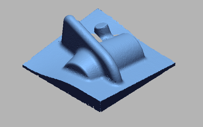
Reverse engineered neutral CAD model formats such as STEP / IGES can be edited in native CAD software. If a neutral CAD format is uploaded in reverse engineering software, a mesh is created. We can take that mesh as a reference and we can live-transfer it to CAD software. It will generate the model tree automatically. We can add or subtract features and also edit geometric features in the CAD model. In the case of Hybrid 3D CAD models, which have both surface features as well as solid features, geometric features such as holes, fillets, ribs, etc. may be edited easily but complex surface features may not be editable.
WORKFLOW
PHASE 1
 Import scan data.png)
Import scan data
 Interactive alignment.png)
Interactive alignment
 Main body developed by revolve.png)
Main body developed by revolve
 Main body developed.png)
Main body developed
 Cutting area developed by extrude.png)
Cutting area developed by extrude
 Cutting area developed by pattern.png)
Cutting area developed by pattern
 Surface developed on cutting edge.png)
Surface developed on cutting edge
 Cutting area developed by pattern_2.png)
Cutting area developed by pattern
 Oil holes developed.png)
Oil holes developed
 Complete cad developed.png)
Complete cad developed
 Solid Works LT started.png)
Solid Works LT started
 Features transfer to solidworks.png)
Features transfer to solidworks
 Circular Pattern Tranferd to solidworks.png)
Circular Pattern Tranferd to solidworks
 Circular Pattern Tranferd to solidworks_2.png)
Circular Pattern Tranferd to solidworks
 Oil holes transfered in Solid works.png)
Oil holes transfered in Solid works
 Complete data transfered to solidworks.png)
Complete data transfered to solidworks
IMAGE
VIDEO
INDUSTRIES WE SERVE
WHAT'S NEXT?
RELATED BLOGS

Scan To Parametric CAD
Parametric cad consists of a history-based feature modeling tree that can be edited to make design
Read more
Scan To Parametric CAD
Parametric cad consists of a history-based feature modeling tree that can be edited to make design
Read more
Scan To Parametric CAD
Parametric cad consists of a history-based feature modeling tree that can be edited to make design
Read more


