Overview
Product development
In product development, 3D scanners and reverse engineering software have become essential. Product development involves reverse engineering of existing parts for improvement and modification or comparing prototypes against CAD models. With a handheld 3D scanner, we can design a physical prototype, 3D scan it, and export the mesh to CAD to optimize the design. In product development, 3D scanners and software save the day by letting us measure tooling and part to inspect them rapidly to pinpoint defects and solve them. Using a portable 3D laser scanner and 3D software will give any controller the capability of gathering measurements of complex shapes to perform inspections by comparing scan data to the reference 3D model.
Product development from existing scan data
We need an existing physical object to get 3D data of fixation points and dimensions in which the new component needs to fit to develop a product. We could break down the product development of a component into three phases: design, manufacturing, and finally quality control. We start with the design and sketches of the existing object that is taken as a reference here. Then a CAD model is created to build the prototype. First article inspection (FAI) lets us take multiple measurements of the first model produced to verify that it matches the original 3D model. If it doesn’t, it goes back to design to find the root cause. This is well suited for aftermarket industries with existing products that need to replace a component or customize it. We can use reverse engineering software or Freeform software. It will allow you to get dimensions from the original product to ensure your new product will perfectly fit.
WORKFLOW
PHASE 1
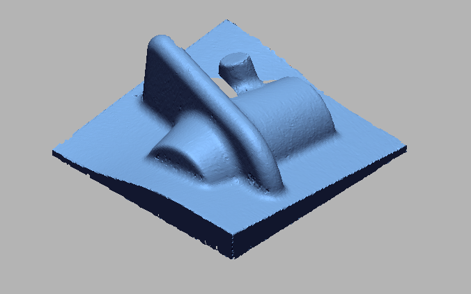
 Import Scan Data.png)
Import scan data
 Scan data by using inertactive alignment.png)
Scan data by using inertactive alignment
 Import Assembly scan data.png)
Import Assembly scan data
 Top Surface developed by meshfit.png)
Top Surface developed by meshfit
 Surface developed on top area.png)
Surface developed on top area
 Bottom surface developed by Loft wizard.png)
Bottom surface developed by Loft wizard
 Surface developed on bottom area.png)
Surface developed on bottom area
 Side surface developed by loft wizard.png)
Side surface developed by loft wizard
 Surface developed on side area.png)
Surface developed on side area
 Back side surface developed by Extrude.png)
Back side surface developed by Extrude
 Surface Developed on Individual scan to get hidden portion.png)
Surface Developed on Individual scan to get hidden portion
 Top surface 3mm offset as per requirements.png)
Top surface 3mm offset as per requirements
 Solidified by Developing all the surfaces.png)
Solidified by Developing all the surfaces
 Selected portion developed as per requirements.png)
Selected portion developed as per requirements
 Mirror the model from RH Tto LH.png)
Mirror the model from RH Tto LH
 Final developed cad model.png)
Final developed cad model
IMAGE
VIDEO
INDUSTRIES WE SERVE
WHAT'S NEXT?
RELATED BLOGS

Scan To Parametric CAD
Parametric cad consists of a history-based feature modeling tree that can be edited to make design
Read more
Scan To Parametric CAD
Parametric cad consists of a history-based feature modeling tree that can be edited to make design
Read more
Scan To Parametric CAD
Parametric cad consists of a history-based feature modeling tree that can be edited to make design
Read more


