Overview
Scan to CAD Comparison
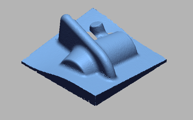
3D scan data can be compared to a CAD model to dimensionally inspect the features like color maps using any type of alignment like best-fit, datum based and feature-based. The 3D scanners and 3D inspection software help us to get a fully parametric CAD model. But we need to check to make sure our model is accurate to the scan, or the design intent assumptions to the specifications. For this process, we need to completely scan the geometry. We import that 3D scanned data (STL or OBJ formats) into the inspection software to create different geometric entities. Now, a parametric solid model is created. We need to check our CAD model is accurate to the original geometry. So, we import the reference model again and use a command called "3D compare" to get a color map and deviation information comparing our CAD model to our original scan. We can use the "Enhanced alignment accuracy" feature to get analysis between two data and the maximum accuracy comparison between 3D scan data to the CAD model.
WORKFLOW
 Import Cad File (15).png)
Import CAD File
 Import 3D Scan Data.png)
Import 3D Scan Data
 Doing initial Allignment for alligning cad wit Scan data (3).png)
Doing initial Allignment for alligning CAD with Scan data
 Doing Best Fit Allignment for precise allignment (3).png)
Doing Best Fit Allignment for precise allignment
 3D Surface Comparison.png)
3D Surface Comparison
 2D Surface Comparison points.png)
2D Surface Comparison points
 Measuring 3D dimensions as per the drawing.png)
Measuring 3D dimensions as per the drawing
 Measuring 3D dimensions as per the drawing with tabular column.png)
Measuring 3D dimensions as per the drawing with tabular column
 2D dimesions takins as per the drawing.png)
2D dimesions takins as per the drawing
 Another Cross section for measuring 2d dimensions.png)
Another Cross section for measuring 2D dimensions
 2D dimensions with table.png)
2D dimensions with table
IMAGE
VIDEO
INDUSTRIES WE SERVE
WHAT'S NEXT?
RELATED BLOGS

Scan To Parametric CAD
Parametric cad consists of a history-based feature modeling tree that can be edited to make design
Read more
Scan To Parametric CAD
Parametric cad consists of a history-based feature modeling tree that can be edited to make design
Read more
Scan To Parametric CAD
Parametric cad consists of a history-based feature modeling tree that can be edited to make design
Read more.jpg)


